Hydraulic Lifters
They are noisy, or my rockers are noisy!
Stock hydraulic lifter cams are designed to be very quiet and smooth running. High performance hydraulic cams are designed for neither, they are designed for power – period.
This means you trade-off quiet and smooth for power and noise, similar to putting on headers. High performance hydraulic roller and flat tappet cams have quicker opening and closing ramps than stock. This is what it takes to produce more power and more noise comes along for no extra charge. The mileage the cylinder block has seen can show up as more wear on the lifter bores. This in conjunction with the faster ramp speeds will cause the lifters and valve train to make more noise than the slower ramp speeds of a stock cam. Where this may become a more common problem is with hydraulic roller lifter applications when the original lifters are re-used. They will be even noisier than the new lifters.
With today’s modern cam grinding equipment and cam lobe designs it is possible to create a mechanical (solid) lifter cam that is mechanically quieter than a high performance hydraulic lifter cam.
Hydraulic lifters were originally designed to take up clearances/lash that mechanical cams had designed into them, to compensate for engine expansion when it heated up. They can be considered a hydraulic shock absorber. Thus, in our opinion, as long as they are used in that capacity (which is about 99.5% of our customers) the amount of pre-load they have is not important!
Where the problems arise is when racers try to make their hydraulic lifters operate like mechanical lifters. They think that the hydraulic cam never requires adjustment and are maintenance free.
But there are “trade-offs” (one of my favorite words). The hydraulic cams would not turn the same RPM as the mechanical cams nor would they produce the same power.
Several years ago we dynoed a 500hp big block with a hydraulic flat tappet cam and then installed mechanical lifters and ran it again. Power improved all the way up and was 20 hp more on the top end. This shows that the cam profile the valve sees is not the same with the hydraulic lifter (shock absorber) as it is with a mechanical lifter. The reason for this is that the lifter was compressing, “absorbing” enough to “tame” the cam action at the valve, resulting in less power. In some applications thi scan be an advantage as I will explain later. Hot rodders, being the dissatisfied bunch that they are, set out to “fix” the perceived problems.
Their first change was to reduce the amount of preload on the lifters so they would not “pump-up”. Pump-up occurs at high rpm when insufficient over-the-nose (open) spring pressure allows the lifter to ski-jump off of the cam lobe just after max lift. This is called lofting. When lofting occurs valve spring pressure on the lifter is momentarily very low, less than engine oil pressure in the lifter. Thus allowing the lifter to “grow” to take up the slack. In a very short time, measured in nanoseconds, the preload is gone and the pumped-up lifter holds the valves open. And you know what that means!
Well, an easy way to cure lifter pump up is to reduce the preload to something like a one quarter turn on the adjusting screw. This way, the lifter is virtually pumped up all the time.
Problem solved, right? Not quite, blow by breath! Now the lifters rattle, well duh! You forgot about the trade-offs. Not only that, but if you are not routinely revving past 7000 RPM, all you got was a noisy valve train. You must have gotten a “bad batch of lifters” – see if that will fly when you call the dealer for a warranty – duh!
Valve springs with higher spring rates go a long way toward reducing lofting and lifter pump-up. So do light weight components such as hollow stem and smaller stem valves, lightweight rockers, and spring retainers and springs. Lightweight springs would be those with smaller coils (lighter) at the top such as beehive type springs.
There are several types of hydraulic lifters made for special applications, none of them will be as quiet as a stock cam & lifters. We sell hydraulic lifters that have faster bleed down rates for special applications. These lifters will not pump up to full length until the engine RPM (oil pump output) is above about 3000 RPM. These “variable duration” lifters allow the use of a larger than normal cam to be used without losing a lot of low end torque, and they will create more vacuum than standard lifters. Their part numbers are HUG 5007 for the magnum engines with roller lifters and part number HUG 5003 for the flat tappet cams, both big block and small blocks.
We also offer the Rhoads line of lifters and they have similar “fast bleed” lifters. Part number RHD 2018 is for LA blocks, and part number RHD 1068 is for Magnum engines.We have slow bleed lifters for the ’93 – ’03 magnum engines that have very slow bleed down and act more like mechanical lifters for use where hydraulic lifters are needed along with higher RPM potential (p/n 5006s).
Adjusting Hydraulic Lifters:
Rotate the camshaft (crankshaft) until the lifter you are adjusting is on the heel (low side, .000" lift) of the cam. Back the rocker arm adjusting screw or pushrod adjusting screw out until you can spin the pushrodby rubbing one finger across it. Now, tighten the adjusting screw until you can no longer spin the pushrod with ONE Now turn the adjusting screw 1½ turns and lock the locking nut down.
If your valve springs are the correct pressure for the cam you have, you will not pump up the lifters. Go to the next lifter and repeat.
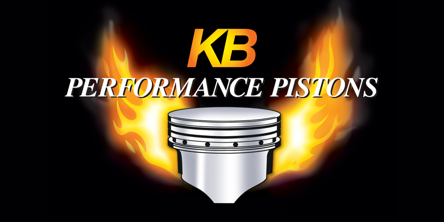
The snap ring that holds the lifter pushrod cup in place is all bent up!
I've only seen this on small blocks as the lifter and pushrod are at angles to each other. When the pushrods are incorrectly installed, they are seated in the "pocket" formed between the retaining ring and the lifter wall.
The above image shows the pushrod incorrectly installed.
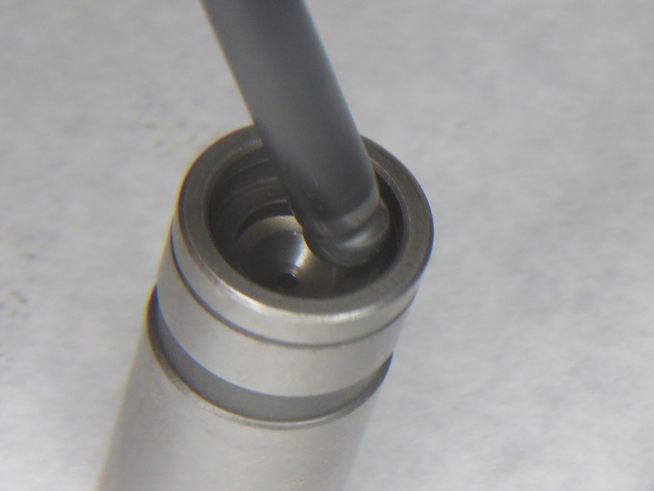
The above image shows the pushrod correctly seated in the lifter.
It seems one of the ways to create the problem is to install the intake manifold first. Installing the pushrods after the manifold is an easy way to create the problem as you annot easily see where the pushrod is seated. To eliminate the problem, install the pushrods first and make sure they are seated properly in the cup.
How To Set a Preload on Hydraulic Lifters:
Talk to people and you get answers. This is how we do it. Assuming you have adjustable rockers or ADJ P. rods! Turn the crankshaft (camshaft) until the exhaust valve in the cylinder you're working on is just starting to lift (opening the exhaust valve). Now adjust the intake pre-load/lash. Adjust the exhaust valve pre-load when the intake lifter (valve) has just closed.
Rotate the crankshaft/camshaft to the correct postition for the lifter you want to pre-load. Loosen rocker/pushrod until the pushrod is loose -- no preload. Ad you can "spin" the pushrod by rubbing 1 (one) finger across it. If you are using and thumb to turn it you are not doing it correctly "Bad dog, bad dog" do it right! Slowly tighten the rocker/pushrod until you cannot "spin" the pushrod. (remember what spinning is!)
All further adjustment is pre-load. The next question is how much should you pre-load the lifter -- (10 people 10 different answers).
|